Dear reader – Fronius DATCOM cabling Benutzerhandbuch
Seite 3
EN
The instructions in this document relating to the cabling of Fronius system monitoring facilities must be strictly adhered to. Only then
can the proper operation and functionality of the products be maintained. Additional information about the products can be found in
the enclosed operating instructions and on our website at http://www.fronius.com - Solar Electronics - Info & Support - Document
Downloads.
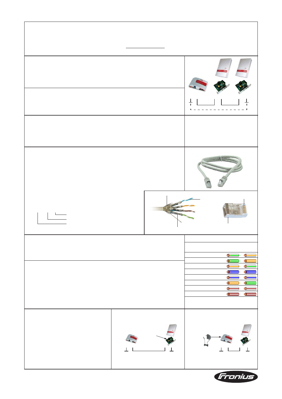
Bus topology and interface
Fronius system monitoring uses a 5-wire RS422 interface consisting of 2 transmit, 2 receive
and 1 ground line (Tx+ / Tx- / Rx+ / Rx- / GND). A system consists of point-to-point connec-
tions that must form a ring. Each node on a ring is connected from OUT to IN by a shielded
8-pin 1:1 cable rated CAT5 or higher.
Forming a ring using terminating plugs
Rings in systems with a total cable length of less than 1000 m can be terminated using
terminating plugs*, which are inserted into the free sockets of the first and last nodes in the
ring.
The terminating plugs are supplied with the Fronius Datalogger.
Forming a ring using a cable
Systems with a total cable length in excess of 1000 m may not be terminated using
terminating plugs. In such cases, a cable must be used to form the ring between the first
and last nodes. The cable length between any two devices must not exceed 1000 m.
Contact Fronius TechSupport in such cases!
Cable
-
Connect the components using an 8-pin screened 1:1 cable with RJ45 plugs
-
Only use shielded cable that conforms to ISO 11801 and EN50173-1:2002 or cable
rated CAT5 or higher (formerly known as CAT5e)
-
The following ready-made cable types are permitted:
F/FTP, S/FTP, SF/FTP, U/FTP, F/STP, S/STP, U/STP, F/UTP, S/UTP
U ............ Unshielded
S ............. Braided shield
F ............. Foil shield
TP .......... Twisted pair
S / S TP
Arrangement of the cores
Shielding for each core pair
Outer shielding of entire cable
Note the following in the case of ready-made cables:
-
Only use shielded cables and plugs, cables must be rated CAT5 or higher
-
The cable shielding must be crimped onto the RJ45 plugs (metal) at both ends
-
The wiring must conform to TIA/EIA T568A or TIA/EIA T568B
Shielding
The cable must be shielded along its entire length and crimped onto both plugs.
IMPORTANT! Components with a serial RS232 or USB interface, such as the Fronius
Interface Box / Card or the Fronius Public Display Box / Card, can establish a connection
to the plant ground via an externally connected device (e.g. PC, PLC, etc.). Components
provided by third parties can also be used to create this type of connection. If two or more
such components are present in the data ring, they must be immediately next to one
another.
Dear reader,
Fronius International GmbH, http://www.fronius.com
IN OUT
IN OUT
IN OUT
Core pair
Core pair shielding
Cable outer shielding
Pin 1
Contacting of outer
cable shield
Contact
T568A
T568B
Fronius Solar Net
1
+12 V
2
GND
3
TX+ IN, RX+ OUT
4
RX+ IN, TX+ OUT
5
RX- IN, TX- OUT
6
TX- IN, RX- OUT
7
GND
8
+12 V
*
*
Wiring conforms to TIA/EIA T568A / B
IMPORTANT!
Do not mix up the RS422 and RS485
interfaces! RS422 is not a bus system!
Ring formation
Power supply for
system monitoring
Inverters are able to supply at least one external
Fronius Box using pins 1, 2, 7 and 8 of the cable.
An additional power supply is needed if:
-
The voltage drop on the cable it too high
(depends on the length or cross-section of
the cable)
-
The inverter is unable to provide enough
power (depends on the number of external
components)
IN OUT
*
Power supply from inverter
12 V DC
supply
IN OUT
IN OUT
*
External power supply via Fronius power supply
External
12 V DC
supply
IN OUT
*
*
Cable: rated CAT 5 or higher
For the products Fronius IG / IG Plus / CL / Galvo / Symo / Primo / Agilo