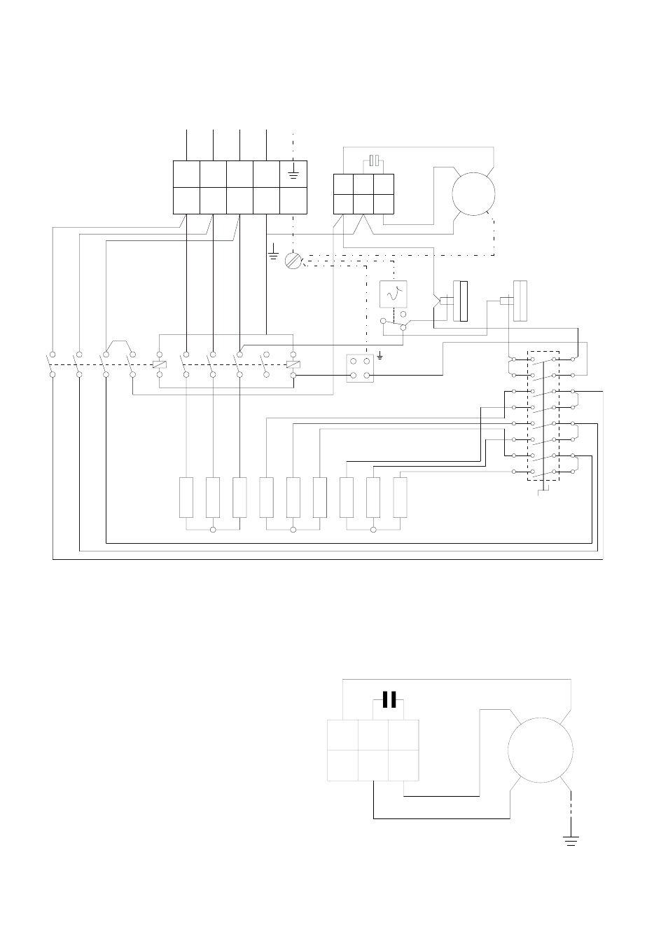
Elektrisches anschlußschema, Klm c 1~ m kl, Tb hw – REMKO ELT 18-S Benutzerhandbuch
Seite 8: Motoranschlußplan
Advertising
8
L1 L2
L3
1 2 3 4 5
N
M1 C1 C2
6 7 8
KLM
C
1~
M
KL
2
1
3
4
5
6
13
14
1
2
C
2
1
3
4
5
6
13
14
2
3
K2
K1
NK
STB
L1 L2 L3 N PE
RT
A2
A1
S
A2
A1
TB
HW
V1
V4
L3
L1
V6
V3
M
H
V5
L2
V2
08/2004
Elektrisches Anschlußschema
KL =
Anschlußklemmleiste
C =
Kondensator
KLM = Motorklemmleiste
M
=
Ventilatormotor
STB = Temperaturbegrenzer
NK
=
Nachkühlthermostat
TB =
Temperaturbegrenzer
K1 =
Schaltschütz
1
K2 =
Schaltschütz
2
RT
=
Thermostatsteckdose
S
=
Betriebsschalter
HW =
Heizwiderstand
Motoranschlußplan
M1 C1
C2
6
7
8
blau
braun
schwarz
KLM
C
M
1~
3 N ~ 50 Hz 400/230
Advertising
Dieses Handbuch ist für die folgenden Produkte bezogen werden: