Elektrisches anschlussschema – REMKO RKL 490 DC S-Line Benutzerhandbuch
Seite 13
Advertising
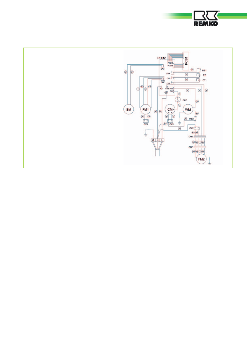
Elektrisches Anschlussschema
Legende
PCB 1 = Steuerplatine
PCB 2 = Hauptplatine
SM
= Swing Motor
FM 1 = Verdampferventilator
FM 2 = Verflüssigerventilator
WM = Kondensatpumpe
CM
= Kompressor
OLP = Kompressorüberhitzungsschutz
CX 1 = Kondensator Verdampferventilator
CX 2 = Kondensator Verflüssigerventilator
CX 3 = Kondensator Kompressor
RT
= Sensor Umlufttemperatur
CT
= Sensor Frostschutz
MS 1 = Microschalter Alarm (Behälter voll)
MS 2 = Microschalter Kondensatpumpe
Farbkennzeichnung
Y
= Gelb
W
= Weiß
R
= Rot
BU
= Blau
BR
= Braun
BK
= Schwarz
GR
= Grau
OR
= Orange
13
Advertising
Dieses Handbuch ist für die folgenden Produkte bezogen werden: