Fronius Grounding Kit Fronius IG Benutzerhandbuch
Seite 24
10
Installing the
‘Grounding Kit
Fronius IG’ in the
DC junction box
40 / 60
(continued)
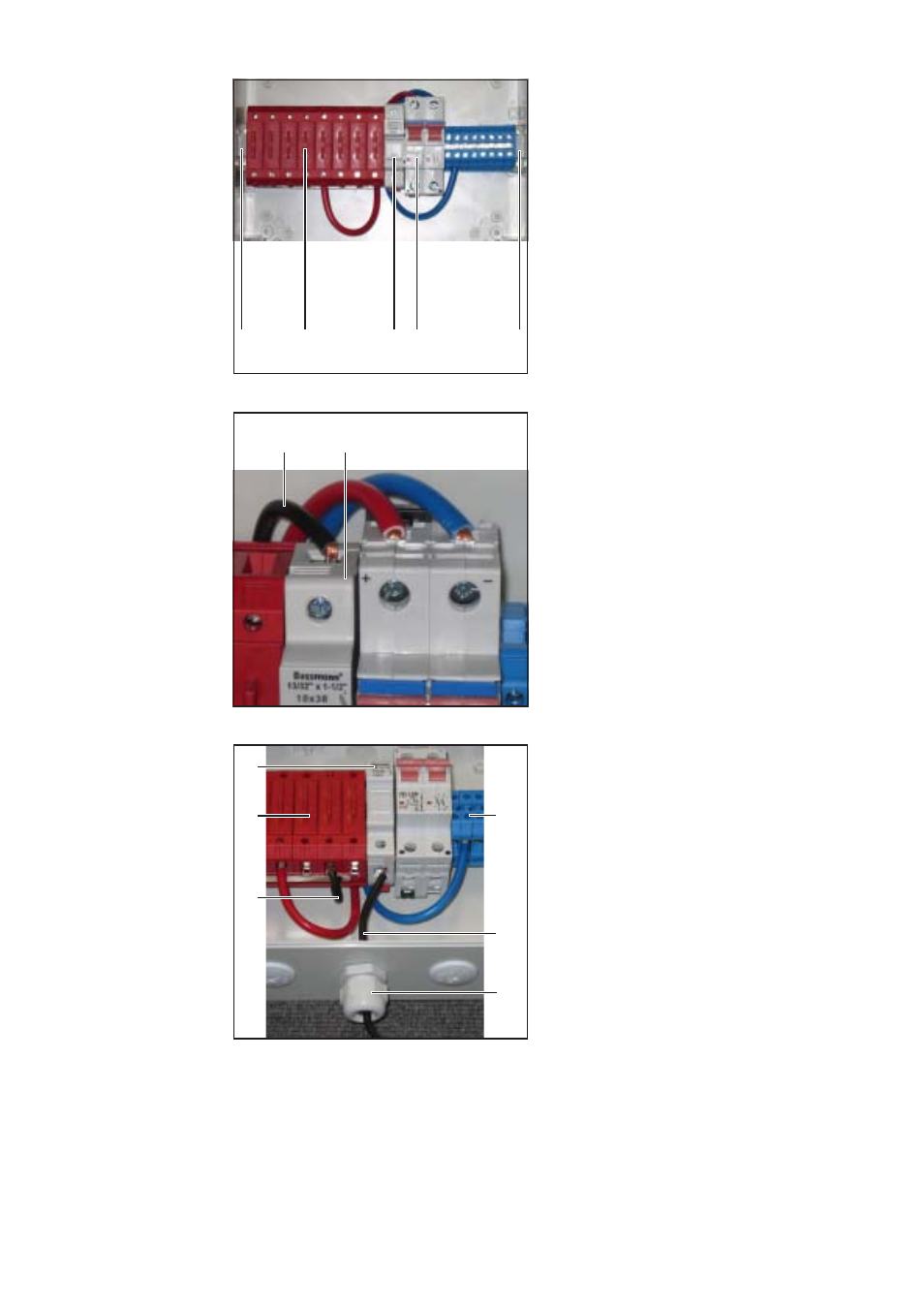
5.
Put the fuse holder (8) between the
DC+ terminals (2) and the DC switch
(4) on the DIN rail as illustrated and
snap in place
6.
Fix the components to the DIN rail
using the two screws on the terminal
holders (1) and (7)
(7)
(4)
(8)
(1)
(2)
Inserting the fuse holder
If the solar module needs to be groun-
ded at the positive pole:
8.
Pass cable (9) from the fuse holder (8)
under the DC+ terminals (2)
9.
Connect cable (9) to a DC+ terminal
Tightening torque = 2 - 2.5 Nm
If the solar module needs to be groun-
ded at the negative pole:
8.
Pass cable (9) from the fuse holder (8)
under the DC- terminals (6)
9.
Connect cable (9) to a DC- terminal
Tightening torque = 0.8 Nm
10. Pass grounding cable with a maximum
cross section of 10 mm² (11) through
the metric screw joint (10)
The grounding cable is not included in
the ‘Grounding Kit Fronius IG’ installa-
tion set.
(10)
(9)
(8)
(2)
Connecting the fuse holder (e.g. if solar module
needs to be grounded at positive pole)
7.
Connect cable with a maximum cross
section of 6 mm² (9) to the fuse holder
(8)
Tightening torque = 2 - 2.5 Nm
The cable is not included in the
‘Grounding Kit Fronius IG’ installation
set.
(8)
(9)
Connecting cable to fuse holder
(11)
(6)
11. Connect the grounding cable (11) to the fuse holder (9)
Tightening torque = 0.8 Nm
12. Fasten PG 16 screw joint (10)