Fronius DC-Freischaltbox 40/60 Benutzerhandbuch
Seite 31
9
5.
6.
7.
5.
5.
5.
5.
6.
7.
7.
7.
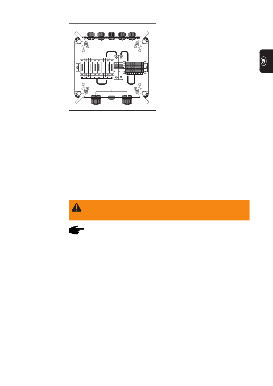
5.
Depending on how many strings there
are, mount a corresponding number
of “M16 screwed conduits with strain
relief device (solar-module side)”, and
fasten them with counter-nuts
6.
Mount the “M25 screwed conduits
with strain relief device (inverter side)”
and fasten them with counter-nuts
7.
Break through the rupture joints (4 x)
Preparations
(continued)
Counter-nut
Counter-nut
1.
Align the DC isolating box 40/60 against the wall in the horizontal, and pencil the
hole-pattern onto the wall as a drilling template
2.
Drill the holes for the dowels
3.
Screw the DC isolating box into the dowels to fasten it to the wall
4.
Close off the rupture joints - and the fixing-screws located inside the rupture joints -
with the 4 cover caps
Important! Mount the DC isolating box 40/60 in such a way that the “M16 solar-module
side” screwed conduits are facing upwards.
Mounting the
DC isolating
box 40/60
Fig.8
Mounting the screwed conduits
Inserting the
fuses
WARNING! Danger from solar-module voltage! Before starting work on the DC
isolating box 40/60, make sure that all strings of solar modules are electrically
dead.
NOTE! For protecting the DC isolating box 40/60 against short circuits, use only
fuses that comply with the “Criteria for selecting the right fuses” above.
Fuse dimensions:
∅ 10.3 x 35 - 38 mm
1.
Open the fuse holder (by pulling it upwards and out)
2.
Insert a suitable fuse
3.
Close the fuse holder, complete with the fuse