Fronius Power Package Benutzerhandbuch
Seite 51
49
EN
DC cable with DC connector kit or with MC4 connectors:
-
without DC cable
-
with DC connector kit, included with each inverter
-
with MC4 connectors on 3 short DC-/DC+ cable pairs, connected to each inverter
-
with MC4 connectors on 4 short DC-/DC+ cable pairs, connected to each inverter
-
with MC4 connectors on 5 short DC-/DC+ cable pairs, connected to each inverter
-
with MC4 connectors on 6 short DC-/DC+ cable pairs, connected to each inverter
Other options are possible (e.g. Fronius Sensor Card / Box).
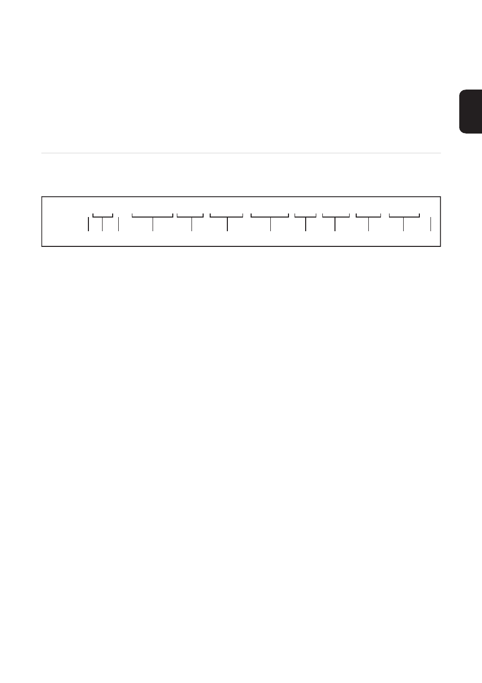
Type key
(1)
Number of inverters
2 / 3 / 4 / 5 / 6
(2)
Highest input power per input in kW
(3)
Position of AC outlet
R = right / L = left
(4)
Overvoltage protection in the AC Combiner
0 = no overvoltage protection in the AC Combiner
T123 = Type 1+2+3 overvoltage protection in the AC Combiner
(5)
AC IN cables
0 = no AC IN cables
AC = with AC IN cables to the inverters, connected to the AC Combiner
(6)
Data communication cables
0 = no data communication cables
DAT = with data communication cables
(7)
CEE 230 V socket
0 = no CEE socket
SSO = with CEE socket
(8)
selected inverter power in kW
15 / 17.5 / 20 / 25 / 27
(9)
Fronius Datamanager 2.0 system monitoring
0 = no system monitoring
DM = Fronius Datamanager 2.0 system monitoring in one inverter
(10)
Fronius Sensor Card
0 = no Fronius Sensor Card
SC = with Fronius Sensor Card
(1) (2) (3)
(4)
(8)
(9)
(11)
(6)
(12)
(5)
FPP x20x-T123-AC-DAT-SSO-xk-DM-SC-T2x-x
(7)
(10)